I’ve been looking at the DAA machine instruction on x86 processors, a special instruction for binary-coded decimal arithmetic.
Intel’s manuals document each instruction in detail, but the DAA description doesn’t make much sense.
I ran an extensive assembly-language test of DAA on a real machine to determine exactly how the instruction behaves.
In this blog post, I explain how the instruction works, in case anyone wants a better understanding.
The DAA instruction
The DAA (Decimal Adjust AL1 after Addition) instruction is designed for use with packed BCD (Binary-Coded Decimal) numbers.
The idea behind BCD is to store decimal numbers in groups of four bits, with each group encoding a digit 0-9 in
binary.
You can fit two decimal digits in a byte; this format is called packed BCD.
For instance, the decimal number 23 would be stored as hex 0x23
(which turns out to be decimal 35).
The 8086 doesn’t implement BCD addition directly. Instead, you use regular binary addition and then
DAA fixes the result.
For instance, suppose you’re adding decimal 23 and 45. In BCD these are 0x23 and 0x45 with the binary sum 0x68, so everything seems straightforward.
But, there’s a problem with carries. For instance, suppose you add decimal 26 and 45 in BCD.
Now, 0x26 + 0x45 = 0x6b, which doesn’t match the desired answer of 0x71.
The problem is that a 4-bit value has a carry at 16, while a decimal digit has a carry at 10. The solution is to add
a correction factor of the difference, 6, to get the correct BCD result: 0x6b + 6 = 0x71.
Thus, if a sum has a digit greater than 9, it needs to be corrected by adding 6. However, there’s another problem.
Consider adding decimal 28 and decimal 49 in BCD: 0x28 + 0x49 = 0x71.
Although this looks like a valid BCD result, it is 6 short of the correct answer, 77, and needs a correction factor.
The problem is the carry out of the low digit caused the value to wrap around.
The solution is for the processor to track the carry out of the low digit, and add a correction if a carry happens.
This flag is usually called a half-carry, although Intel calls it the Auxiliary Carry Flag.2
For a packed BCD value, a similar correction must be done for the upper digit.
This is accomplished by the DAA (Decimal Adjust AL after Addition) instruction.
Thus, to add a packed BCD value, you perform an ADD instruction followed by a DAA instruction.
Intel’s explanation
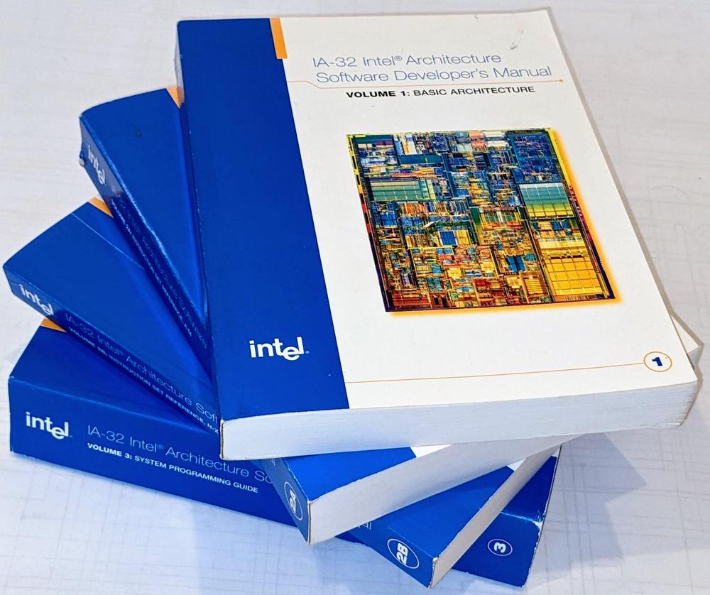
The Intel Software Developer’s Manuals. These are from 2004, back when Intel would send out manuals on request.
The Intel 64 and IA-32 Architectures Software Developer Manuals provide detailed pseudocode specifying exactly what each machine instruction does.
However, in the case of DAA, the pseudocode is confusing and the description is ambiguous.
To verify the operation of the DAA instruction on actual hardware, I wrote a short
assembly program to perform DAA on all input values (0-255) and all four combinations of the carry and auxiliary flags.3
I tested the pseudocode against this test output.
I determined that Intel’s description is technically correct, but can be significantly simplified.
The manual gives the following pseudocode; my comments are in green.
IF 64-Bit Mode
  THEN
    #UD;  Undefined opcode in 64-bit mode
  ELSE
    old_AL := AL; AL holds input value
    old_CF := CF; CF is the carry flag
    CF := 0;
    IF (((AL AND 0FH) > 9) or AF = 1) AF is the auxiliary flag
      THEN
        AL := AL + 6;
        CF := old_CF or (Carry from AL := AL + 6); dead code
        AF := 1;
      ELSE
        AF := 0;
      FI;
    IF ((old_AL > 99H) or (old_CF = 1))
      THEN
        AL := AL + 60H;
        CF := 1;
      ELSE
        CF := 0;
    FI;
FI;
Removing the unnecessary code yields the version below, which makes it much clearer what is going on.
The low digit is corrected if it exceeds 9 or if the auxiliary flag is set on entry.
The high digit is corrected if it exceeds 9 or if the carry flag is set on entry.4
At completion, the auxiliary and carry flags are set if an adjustment happened to the corresponding digit.5
(Because these flags force a correction, the operation never clears them if they were set at entry.)
IF 64-Bit Mode
  THEN
    #UD;
  ELSE
    old_AL := AL;
    IF (((AL AND 0FH) > 9) or AF = 1)
      THEN
        AL := AL + 6;
        AF := 1;
      FI;
    IF ((old_AL > 99H) or CF = 1)
      THEN
        AL := AL + 60H;
        CF := 1;
    FI;
FI;
History of BCD
The use of binary-coded decimal may seem strange from the modern perspective, but it makes more sense looking at
some history.
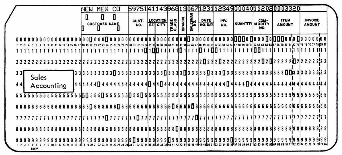
In 1928, IBM introduced the 80-column punch card, which became very popular for business data processing.
These cards store one decimal digit per column, with each digit indicated by a single hole in row 0 through 9.6
Even before digital computers, businesses could perform fairly complex operations on punch-card data using electromechanical equipment such
as sorters and collators. Tabulators, programmed by wiring panels, performed arithmetic on punch cards using
electromechanical counting wheels and printed business reports.
These calculations were performed in decimal.
Decimal fields were read off punch cards, added with decimal counting wheels,
and printed as decimal digits.
Numbers were not represented in binary, or even binary-coded decimal. Instead, digits were represented by the
position of the hole in the card, which controlled the timing of pulses inside the machinery. These pulses
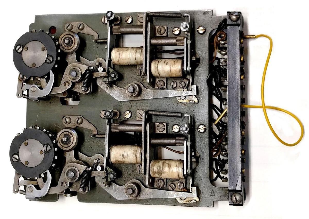
rotated counting wheels, which stored their totals as angular rotations, a bit like an odometer.
A counter unit from an IBM accounting machine (tabulator). The two wheels held two digits. The electromagnets (white) engaged and disengaged the clutch so the wheel would advance the desired number of positions.
With the rise of electronic digital computers in the 1950s, you might expect binary to take over.
Scientific computers used binary for their calculations, such as the IBM 701 (1952).
However, business computers such as the IBM 702 (1955) and the IBM 1401 (1959) operated on decimal digits, typically
stored as binary-coded decimal in 6-bit characters.
Unlike the scientific computers, these business computers performed arithmetic operation in decimal.
The main advantage of decimal arithmetic was compatibility with decimal fields stored in punch cards.
Second, decimal arithmetic avoided time-consuming conversions between binary and decimal, a benefit for applications
that were primarily input and output rather than computation.
Finally, decimal arithmetic avoided the rounding and truncation problems that can happen if you use floating-point numbers for accounting calculations.
The importance of decimal arithmetic to business can be seen in its influence on the COBOL programming language,
very popular for business applications.
A data field was specified with the PICTURE clause, which specified exactly how many decimal digits each
field contained.
For instance PICTURE S999V99 specified a five-digit number (five 9’s) with a sign (S) and implied decimal point (V).
(Binary fields were an optional feature.)
In 1964, IBM introduced the
System/360 line of computers, designed for both scientific and business use, the whole
360° of applications.
The System/360 architecture was based on 32-bit binary words.
But to support business applications, it also provided decimal data structures.
Packed decimal provided variable-length decimal fields by putting two binary-coded decimal digits per byte.
A special set of arithmetic instructions supported addition, subtraction, multiplication, and division of decimal values.
The System/360 Model 50 in a datacenter. The console and processor are at the left. An IBM 1442 card reader/punch is behind the IBM 1052 printer-keyboard that the operator is using. At the back, another operator is loading a tape onto an IBM 2401 tape drive. Photo from IBM.
With the introduction of microprocessors, binary-coded decimal remained important.
The Intel 4004 microprocessor (1971) was designed for a calculator, so it needed decimal arithmetic, provided
by Decimal Adjust Accumulator (DAA) instruction.
Intel implemented BCD in the Intel 8080 (1974).7 This processor implemented an Auxiliary Carry (or half carry) flag and a DAA instruction.
This was the source of the 8086’s DAA instruction, since the 8086 was designed to be somewhat compatible with the 8080.8
The Motorola 6800 (1974) has a similar DAA instruction, while the 68000 had several BCD instructions.
The MOS 6502 (1975), however, took a more convenient approach: its decimal mode flag automatically performed BCD corrections.
This on-the-fly correction approach was patented, which may explain
why it didn’t appear in other processors.9
The use of BCD in microprocessors was probably motivated by applications that interacted with the user in decimal,
from scales to video games.
These motivations also applied to microcontrollers.
The popular Texas Instruments TMS-1000 (1974) didn’t support BCD directly, but it had special case instructions like
A6AAC (Add 6 to accumulator) to make BCD arithmetic easier.
The Intel 8051 microcontroller (1980) has a DAA instruction.
The Atmel AVR (1997, used in Arduinos) has a half-carry flag to assist with BCD.
Binary-coded decimal has lost popularity in newer microprocessors, probably because the conversion time between
binary and decimal is now insignificant.
The ill-fated Itanium, for instance, didn’t support decimal arithmetic.
RISC processors, with their reduced instruction sets, cast aside less-important
instructions such as decimal arithmetic;
examples are ARM 1985), MIPS (1985), SPARC (1987), PowerPC (1992), and RISC-V (2010).
Even Intel’s x86 processors are moving away from the DAA instruction; it generates an invalid opcode exception in x86-64 mode.
Rather than BCD, IBM’s POWER6 processor (2007) supports decimal floating point for business applications that use decimal arithmetic.
Conclusions
The DAA instruction is complicated and confusing as described in Intel documentation. Hopefully the simplified
code and explanation in this post make the instruction a bit easier to understand.
Follow me on Twitter @kenshirriff or RSS for updates.
I’ve also started experimenting with Mastodon recently as @[email protected].
I wrote about the 8085’s decimal adjust circuitry in this blog post.


