


We shall start with a bit of history:
- 2016: Building a Low Power PC on Skylake – 10 watts idle
- 2019: 9w Idle – Creating a low power home NAS / file server with 4 Storage Drives
- 2021: (no write-up) – 11 watts using an Intel i3-10320 on a Gigabyte H470M DS3H
Not all my systems have been so successful. In 2022 I measured a couple other systems at 19 watts and 27 watts as part of Curbing the “Gas-Guzzling” tendencies of AMD Radeon with Multi-Monitor . While I did manage to get that 27 watt AMD system down in power some time later, not every CPU/motherboard combo is destined for the 10 watt ballpark.
—
Before going further, the 7 watt figure for this system was before storage has been added. The 7 watts (measured at the wall) includes:
- Motherboard (Intel H770)
- CPU (Intel i5-12400)
- 64GB RAM
- SSD (booting Ubuntu Server 23.04)
- PSU (Corsair)
- C-States set up in BIOS so that it reaches C8
- powertop with auto-tune (which disabled the USB keyboard when the port went to sleep)
Note that if I don’t allow powertop to disable the keyboard, I get 8 watts measured at the wall.
—
Let’s get into detailed specs and component choices. This time around I had the following goals:
- low idle power
- reasonable CPU performance for compression
- able to handle 12 hard drives + at least 1 NVMe
- capacity to (eventually) convert those 12 hard drives to 6 NVMe + 6 SSD SATA
- keep costs under control – since a motherboard purchase would be required, try to stick with DDR4 and reuse a CPU I already have.
Putting together a new system with the hopes of getting in the ballpark of the 10 watt range *measured from the wall* is often not only a challenge, but a bit of a gamble. Sometimes you just have to take your best educated guesses in terms of components, build your rig, tune what you can, and let the chips fall where they may.
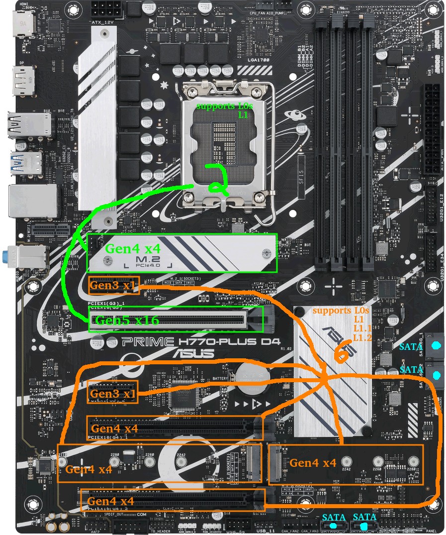
Motherboard – ASUS Prime H770-Plus D4
Before I begin, here is a quick look at the motherboard layout. The GREEN CPU-connected slots and ORANGE chipset-connected slots will become relevant throughout this write-up.
At the time of writing, widely available consumer options were motherboards in the Intel 600/700-series and AMD 500/600-series.
One of my goals above was the capacity for an eventual 6 NVMe drives.
Digging into deeper details as to why this can be a challenge (feel free to skip this section)…
Problem: There are 0 consumer motherboards with 6x M.2 slots that can all be used at the same time in PCIe mode. On AMD the MEG X570S Unify-X Max *looks* like it does, but check the manual and you’ll find that if you try to populate all 6, the last one has to be a SATA variant. The ASRock Z790 PG Sonic also has 6 slots, but you can only use 5 of them (with a legitimate excuse: they offer a Gen5 NVMe slot but it comes with an either/or caveat).
Why This Problem Exists: There are chipset lane limitations on consumer boards. Assuming I want the ability to run all M.2 in Gen4x4 and assuming a manufacturer were actually willing to devote all the lanes to M.2 NVMe slots (they’re not), AMD X570 and Intel B760 would max at three M.2 slots, with AMD B650 and Intel H670/Q670/Z690/W680 managing four. Five M.2 slots is possible on AMD X670 and Intel H770 boards. Six on a Z790 board. Beyond that, extraordinary measures like robbing the main PCIE slot of lanes would be required. If sheer M.2 count were desired, manufacturers could run theoretically run lanes in Gen4x2 or add some Gen3 M.2 slots, but at that point they’ve created a *very* niche product.
The Solution: PCI-E to M.2 adapters became necessary. Now when searching for a motherboard, it became a matter if adding the M.2 slots included to any available PCI-E slots capable of x4 or higher. My options were now limited to AMD X570, Intel H770, and Intel Z790 motherboards. Note that while using bifurcation is a possibility on some motherboards to get more than 1 NVMe out of the main PCIe slot, I decided not to rely on it.
I decided to go the Intel route for a few reasons:
- Chipset TDP: 600/700-series Intel chipsets all have a 6W TDP, whereas the TDP of the AMD X670 chipset is pretty high (7w+7w). AMD chipset power consumption has concerned me for a while, as previous X570 chipsets had a TDP of 11w and needed a fan.
- Chipset Speed: Intel H670/Q670/W680/Z690/H770/Z790 chipsets have a DMI 4.0 x8 link to the CPU. AMD X570/B650/X670 have a PCIe 4.0 x4 link to the CPU. Theoretical throughput on the Intel should be twice as much as AMD (16GB/s vs 8GB/s).
- I already had 64GB of DDR4 that the Intel system could use. AMD 600-series chipsets are all DDR5-only.
- I already had an Intel 12th Gen CPU.
- I’ve yet to see any positive discussion around AM5 power consumption. At all. Update: as I was writing this, news actually came out about AMD 7000-series CPUs burning/bulging where the motherboard socket pins meet the CPU. Yeah, sorry AMD, not this time.
So Intel it was. After checking out available DDR4 motherboards on the market, I quickly narrowed options to 2 manufacturers: MSI and ASUS.
Don’t care about the board comparisons? Feel free to skip this.
The enticing MSI boards were the PRO Z790-P WIFI DDR4 and Z790-A WIFI DDR4. Nearly identical on the surface, except the “A” is a little more premium (audio, rear ports, heatsinks, power phases, etc). Pros/cons:
- Pro: 4x M.2 (Gen4x4) + 1x PCIE Gen5x16 + 1x PCIE Gen4x4 supports a total of 6 Gen4 NVMe
- Pro: 2x PCIE Gen3x1 extra
- Pro: 6 SATA ports
- Con: Intel 2.5G LAN (known to be problematic and buggy)
- Con: I’m not a fan of the MSI BIOS
- Con: My current B660 board that results in higher idle consumption than expected is an MSI.
Attractive ASUS options were the Prime H770-Plus D4 and Prime Z790-P D4 (optional WIFI edition). Getting into the TUF, Strix, or ProArt was just too expensive.
I’ll start by listing pros/cons for the H770-Plus:
- Pro: 3x M.2 (Gen4x4) + 1x PCIE Gen5x16 + 2x PCIE Gen4x4 supports a total of 6 Gen4 NVMe
- Pro: 2x PCIE Gen3x1 extra
- Con: Only 4 SATA ports
Pro: 2.5G Realtek Network Adapter (preferable to Intel 2.5G LAN these days)(see comments)The Z790-P D4 is similar except it has more power phases, better heatsinking, more USB ports, extra fan header, and for our purposes…:
- +1 PCIE Gen4x4
- -1 PCIE Gen3x1
Ultimately the ASUS Prime H770-Plus D4 was about $100 cheaper at the time and is what I chose.
One upside I’ve found with “cheaper” boards is they tend to have fewer components and thus less vampire power drain at idle, though this isn’t always a certainty.
CPU – Intel i5-12400 (H0 stepping) – Alder Lake
I already had this CPU as part of a previous desktop build. At the time it was chosen for the desktop system because:
- it had AV1 hardware decode
- it had the highest performance available from the Intel lineup of the 12th generation that avoids the E-core silicon overhead
- in that build, I was getting a new motherboard with 2xDP anyway, and going older-gen didn’t make sense to me.
That desktop build turned out to be a disappointment, and ranks as one of my least favorite builds.
Some details…
I had issues where sometimes only 1 of 2 DP-attached monitors would wake in Linux which meant I had to either pull/reconnect the other DP connector, or manually suspend/resume the system so it could try again.
Another issue was that rebooting between Windows/Linux sometimes caused odd issues which necessitated a full poweroff/restart.
Hardware decode on Ubuntu using Wayland is still problematic and when programs tried to use it to play video, problems would ensue.
Finally, unlike my previous Intel systems which could all be brought down near the 10 watt mark, this one was idling at 19 watts, though I suspected the MSI motherboard I was using may have been a factor.
Most of the headaches I experienced were related to the GPU and display. Since I was about to build something server-oriented, that was no longer a factor.
MEMORY – 64GB DDR4-3200
Here’s what I used:
- 2x16GB Kingston HyperX dual-rank (Hynix DJR)
- 2x16GB Kingston HyperX single-rank (Hynix CJR)
This was memory I already had. I ran the 4 sticks of memory at the XMP profile of the dual-rank kit which was 16-18-18-36. Everything else was essentially left to the defaults except that I ran the RAM at 1.25 volts (higher than stock 1.20, but lower than the XMP 1.35v setting). TestMem5 and Memtest86 showed stability at 1.22v, though testing this memory on previous motherboards had shown 1.22v to be unstable, so for a little extra buffer when it comes to stability I boosted the voltage to 1.25v.
Boot Drive – Sandisk Ultra 3D 1TB SSD
This component wasn’t deliberately chosen. When I wanted a fresh Ubuntu Server install for testing, this happened to be the only SSD I had kicking around that wasn’t currently being used. I was going to be doing a lot of A/B testing on PCIE and NVMe devices, so installing Ubuntu 23.04 to a SATA SSD made sense to keep PCIE slots free.
Note that after testing, the main OS was to be run on a Samsung SSD 970 EVO Plus 500GB NVMe. Not much to say except that Samsung stuff tends to reliably go into low power modes.
Having used both drives, I can’t measure any power difference between them in my testing. Tom’s Hardware tested the Samsung idle at 0.072 watts (via ASPM/APST), and Anandtech tested the Sandisk Ultra 3D idle to be 0.056 watts (via ALPM). Both are well below the 1W resolution of my Kill-A-Watt meter.
PSU – Corsair RM750
As much as this 750W PSU may appear to be overkill for a system intended to sit around 10 watts, when 12 drive motors spin up at the same time, the instantaneous load is likely to be quite high. Seagate states 2A/3A DC/AC peak currents on the 12V rail for one of their 10TB 3.5″ drives. Even peak random read/writes can clock in at over 2A.
This bursty power demand has the potential to be problematic if the PSU isn’t up to the task. If an array of 6 drives collectively pull 150-200 watts at the same moment the CPU spikes to pull a peak 120W, that’s a jump from around 10 watts idle to around 400 watts. This could easily cause an instantaneous voltage dip – if it dips enough to cause an immediate crash/reboot it’s probably not a big deal, but if it dips just enough that data is corrupted during a memory refresh or when another drive is mid-write… that’s a more painful problem. Oversizing the PSU to some degree (or adding some in-line capacitors to the power rails) makes sense.
Fortunately, despite operating outside of the peak efficiency range, much of the Corsair RM series is pretty efficient across a wide range.
Power Measurements – Initial
A few important bits:
- Power measured from the wall
- Intel PowerTOP was used to auto-tune settings
- Ubuntu Server 23.04
A few potentially-important BIOS bits:
- CPU C-states were enabled in the BIOS (C10)
- ASPM was enabled with everything set to L1
- RC6 (Render Standby) enabled
- Aggressive LPM Support enabled (ALPM)
- DISABLED: HD Audio, Connectivity Mode, LEDs, GNA Device, Serial Port
9-10 watts was the consumption when the display output was on.
7 watts was the consumption once the display turned off (consoleblank=600 kernel boot parameter for a 600s timer), which is where this system sits most of the week.
8 watts was the consumption if the USB keyboard power management was disabled. If you don’t SSH into the server from elsewhere, spending the extra watt for keyboard use might be necessary.
Problematic Power Measurements – Loaded up with spinning rust (spun-down)
As mentioned in the beginning, I started with 12 hard drives. Half were 2.5″ and the other half were 3.5″. Because the motherboard only has 4 SATA ports, a SATA controller and a port multiplier were used to handle the remaining drives. Additionally, 4 NVMe drives were used early on: one of them, a Western Digital SN770 had a tendency to get quite hot even at idle which indicates it probably wasn’t going into a low power mode.
With all the equipment connected, at idle, with display off, and with the 12 drives spun down to standby, I was shocked to see that my idle power consumption had gone from 7 watts all the way up to a whopping 24-25 watts. Far too much! Something was amiss.
Power Consumption Puzzles – High Power Investigation and Diagnosis
I disconnected the hard drives and started testing components one at a time. These were fairly crude tests meant to get a rough idea as to the culprit, so numbers here aren’t precise.
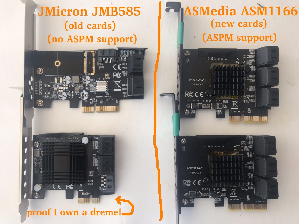
I quickly discovered that the JMB585 SATA controller I was using caused power consumption to increase by something in the 6-10 watt range (precise measurements in a later section). The controller itself is only supposed to take a couple watts, and the tiny heatsink stayed cool, so there was obviously more going on. Where was the power going?
I decided to watch the CPU package C-states. Without the JMB585 SATA controller, the system hit C6. When the JMB585 was reconnected, the best the system hit was C3. Ah ha! But why? Turns out that if a PCIE-connected device won’t go into ASPM L1, the CPU won’t go into as deep a sleep. The JMB585 controller cards don’t seem to have ASPM support.
A little further experimentation revealed something else that I hadn’t known, and it has to do with C6 vs C8. The system will only hit C8 if there’s nothing hooked up to the CPU-attached PCIE lanes. In other words, if anything is plugged in to the top PCIE slot or the top NVMe slot, C6 is the maximum. The power consumption difference between C6 and C8 *seemed* to be less than a watt in a simple test.
So while C8 would be a luxury, hitting C6 was a must. C3 uses too much power. If SATA controllers were going to prevent the CPU from hitting the best power saving states, I started to wonder whether I should have been looking for a motherboard with 6-8 SATA ports so that I wouldn’t have to rely on add-on controllers…
A little searching for SATA HBAs showed that while there aren’t many options here, the ASM1166 SATA controller should support ASPM L1, though the firmware has to be flashed for it to work properly (and to work at all on newer Intel boards). This was something I’d have to order: I have Marvel and JMicron spares, but they don’t support ASPM. I’d actually been avoiding ASMedia for years, but out of necessity they were now getting another chance: I ordered a couple ASM1166 6 port SATA controllers.
Aside: BadTLP, Bad! AER Bus Errors from the pcieport
Worth a mention… During initial testing with a WD Black SN770 (Gen4 NVMe), I found a problem when the primary (top CPU-attached) PCIE and NVMe ports were used. Running dmesg resulted in output littered with stuff like:
pcieport 0000:00:06.0: AER: Corrected error received: 0000:02:00.0
nvme 0000:02:00.0: PCIe Bus Error: severity=Corrected, type=Physical Layer, (Receiver ID)
pcieport 0000:00:06.0: PCIe Bus Error: severity=Corrected, type=Data Link Layer, (Transmitter ID)
pcieport 0000:00:06.0: AER: Error of this Agent is reported first
nvme 0000:02:00.0: [ 6] BadTLP
…after much trial-and-error I found that if the “PEG – ASPM” BIOS setting was set to [Disabled] or [L0s] there were no errors.
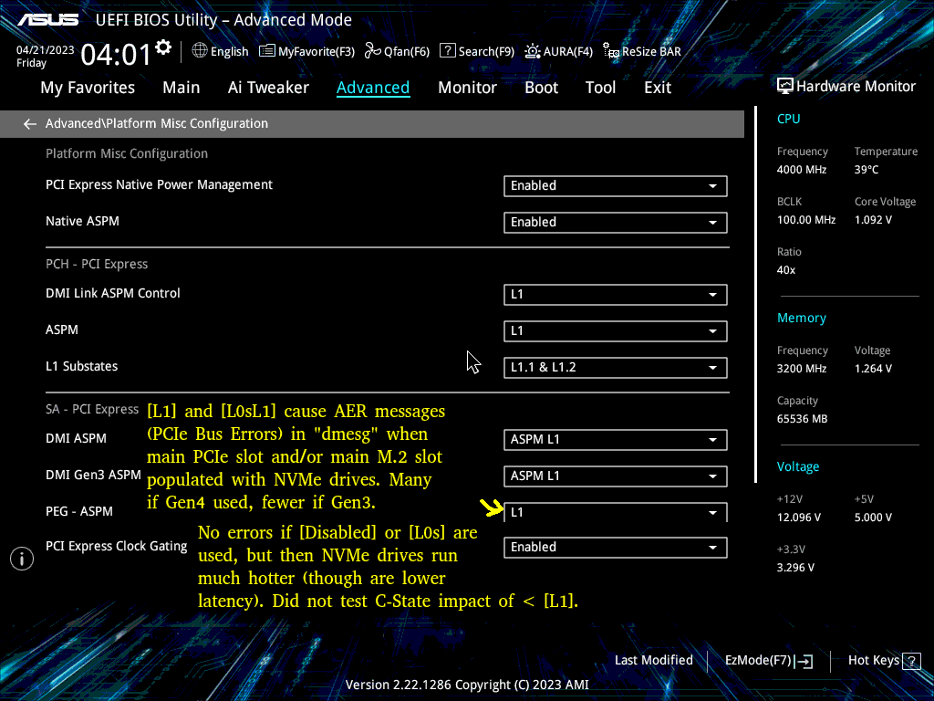
Of course, this was a bad option, as [L1] is crucial for power savings. If [L1] or [L0sL1] were used, the only option was to set the Link Speed of those ports to [Gen3], which didn’t stop the errors, but reduced them substantially.
Some research showed the root cause can be any number of things. Because swapping the motherboard or CPU wasn’t a pleasant thought, my best hope was swapping to a different brand of NVMe.
I ordered some Crucial P3 NVMe drives. This turned out to be a successful endeavor: with the WD drives replaced by the Crucial drives, I was no longer getting any errors, though keep in mind these are Gen3 drives.
Power Consumption Puzzles – Finding L1.1 and L1.2 to be enabled on chipset-connected ports only
When I had the 2 Crucial P3 NVMe drives installed in the CPU-connected PCIEx16 slot and the top M2 slot, I noticed higher idle temps than expected. While the NAND sat at about 27-29C, the controllers were reporting 49-50C – much higher than I expected for these particular drives.
I moved the one from the PCIEx16 slot to a chipset-connected PCIEx4 slot. An interesting difference between these drives showed up via lspci -vvv:
CPU-connected M2 slot: L1SubCtl1: PCI-PM_L1.2- PCI-PM_L1.1- ASPM_L1.2- ASPM_L1.1-
Chipset-connected PCIE slot: L1SubCtl1: PCI-PM_L1.2+ PCI-PM_L1.1+ ASPM_L1.2+ ASPM_L1.1+
L1 sub-states only seem to get enabled on the chipset-connected slots. Unfortunate, but it does seem to coincide with the available BIOS settings in the screenshot above.
Let’s reference that motherboard picture again to show the situation:
I put both NVMe drives on chipset-connected PCIE slots. Now both showed L1.1+/L1.2+ and both controller temps were down from the 49-50C range to 38-41C.
Unfortunately when attempting various A/B tests using these 2 Crucial NVMe drives with different slot configurations and various BIOS settings, I saw very inconsistent behavior in terms of temperature, though it’s worth noting the JMB585 and an NVMe boot drive were also connected during these tests. For example, both drives might idle at around 40C until a soft reboot at which point 1 (or both) might now idle at the 50C range. Sometimes it seemed possible to keep 1 drive on the CPU-connected M.2 and retain 40C temperatures on both drives as long as the x16 slot wasn’t populated. Presumably I was hitting some sort of bug. The Samsung boot NVMe seemed to keep a consistent idle temperature regardless of what was happening with the Crucial NVMe drives, so I suspected the Crucial drives themselves are at least partly to blame.
Interestingly, sometimes one (or both) controller temps would drop all the way down to the 29C range when on the chipset-connected slots. Since trying to find a low-power 4TB NVMe replacement for the Crucial P3 wasn’t a realistic goal, my best hope at this point was that the ASPM-incompatible JMicron JMB 585 was somehow to blame, since it was soon to be replaced with the ASPM-compatible ASMedia ASM 1166.
Late Update: I unfortunately didn’t keep track of temperatures throughout the rest of the testing, and heatsinks/airflow between drives have all been jumbled around. But for whatever it’s worth, In the final build, my Crucial P3 controller temps are 31-34C, and NAND temps are 23-24C.
Power Consumption Puzzles – Swapping from the JMB585 to the ASM1166.
After a couple weeks the ASM1166 arrived. First a couple bits regarding the card which you might find helpful if you’re considering it…
I began with a firmware flash – ASM1166 cards often have old firmware which doesn’t work with Intel 600-series motherboards and from what I understand can have issues with power management. Newer firmware can be found floating around in various places, but I decided to grab a copy from SilverStone (“fix compatibility issue” in the Download section of https://www.silverstonetek.com/en/product/info/expansion-cards/ECS06/) and followed the instructions at https://docs.phil-barker.com/posts/upgrading-ASM1166-firmware-for-unraid/ . Note that the SilverStone files had an identical MD5 to firmware I found by following the thread at https://forums.unraid.net/topic/102010-recommended-controllers-for-unraid/page/8/#comment-1185707 .
For anyone planning to purchase one of these ASMedia cards, I should note that like most SATA controllers and HBAs out there, the quality really varies. One of my cards had a heatsink that was on a bit crooked: the thermal pad was thick enough to prevent it from shorting nearby components, but be aware that these products can be really hit-and-miss. This is one of the situations where paying a little more to buy from somewhere with a good return policy can be prudent.
I did quite a bit of A/B testing, so here is a quick “JMicron JMB585 vs ASMedia ASM1166” in terms of total system power consumption, though it may only be applicable to this platform (or perhaps even this specific motherboard).
DRIVELESS
First, power consumption without any drives connected to the cards (the SATA SSD boot drive is connected to the motherboard) to get a baseline. PowerTOP used on all devices except for the keyboard (adding +1 watt). Measurements after the display output went to sleep.
- 8 watts – No SATA controller – C8 power state
- 9 watts – ASM1166 on a chipset-connected x4 slot – C8 power state
- 12 watts – JMB585 on the CPU-connected x16 slot – C3 power state
- 15 watts – JMB585 on a chipset-connected x4 slot – C3 power state
- 22 watts – ASM1166 on the CPU-connected x16 slot – C2 power state
The ASM1166 does well here if plugged into a chipset-connected slot (only +1 watt), but does horribly if connected to the main PCI-E slot (+14 watts) where the CPU package power state plummets to C2. Shockingly, the JMB585 behaves in an opposite manner where it’s consumption is lower on the CPU-connected slot (and it didn’t cause C2) – however, you’ll soon see that things change when drives are actually connected…
I did additional testing with the controllers, including playing “musical chairs” with a couple NVMe drives to see if multiple devices would throw a wrench into things, but nothing unexpected took place so I’ll skip those details.
ADDING DRIVES
With baseline measurements complete, next it was time to actually put some drives on these controllers. The SATA SSD boot drive stayed on the motherboard, 2 NVMe drives were added to the mix (chipset-connected unless otherwise noted), and 4 of the 2.5″ SATA hard drives were placed on the controller. I’ll list the “spun down” consumption after the hard drives went into standby – “spun up” was exactly 2 watts higher in every test while the drives were idle.
- 10 watts – ASM1166 on a chipset-connected x4 slot – C8 power state
- 11 watts – ASM1166 on a chipset-connected x4 slot with 1 NVMe moved to the CPU-connected x16 slot – C6 power state
- 11 watts – 2x ASM1166 on chipset-connected x4 slots, with only 1 NVMe drive – C8 power state
- 16 watts – JMB585 on a chipset-connected x4 slot – C3 power state
- 24 watts – JMB585 on CPU-connected x16 slot – C2 power state
With 4 drives connected via a chipset-connected slot, the ASM1166 adds +2 watts to system power consumption, whereas the JMB585 adds +8 watts. No contest.
An additional benefit is that I was able to use both of the ASM1166 cards in the system, whereas attempting to use both of my JMB575 cards at the same time resulted in the system refusing to boot, though that could be a platform or motherboard-specific issue.
There is a trade-off though – I always found the JMB585 to be rock-solid reliable, including when paired with a JMB575 port multiplier. My past experience with ASMedia SATA controllers has been less than stellar: reliability with the ASM1166 remains to be seen, but at the very least it’s a bad candidate for a port multiplier since it doesn’t support FBS (only CBS).
A couple other minor hiccups that presented with the ASM1166:
- When removing/reinserting the NVMe boot drive, a BIOS message appeared claiming that it couldn’t boot due to GPT corruption. The ASM1166 cards had to be temporarily removed for the BIOS to “find” the NVMe boot drive again (after which they could be reinstalled).
- The ASM1166 cards claim to have a *lot* of ports – this causes additional boot time as Linux has to iterate through all of them.

Update: SATA and SSD Brands
One of the comments mentioned an older Samsung 840 PRO SSD limiting to C3 whereas a Crucial Force GT SSD allowed C8. While those are older drives, I still found this a bit surprising. It was worth investigating.
I used the H770 as a testbed with a Samsung 850 EVO SATA SSD boot drive along with a Crucial P3 NVMe and built a custom kernel to allow the Realtek network adapter to reach L1.2. No ASM1166, just using the Intel onboard SATA. I reached C10 after running powertop with auto-tune and allowing the display to sleep.
I then added a Patriot P210 SATA SSD. Stuck at C6.
I removed the Patriot P210 and tried a 4TB 2.5″ Seagate SATA HDD. C10. Swapped it for an 8TB 3.5″ Seagate SATA HDD. C10. Swapped that for a 14TB Toshiba SATA HDD. C10. Added a 1TB Sandisk Ultra 3D SATA SSD to the Toshiba HDD. C10.
Later test: a 4TB Crucial MX500. C10.
The lesson here: we clearly need to be picky about SATA SSDs. Feel free to leave a comment with good/bad ones you come across.
Power Consumption Puzzles – Conclusion
A few important bits if aiming for low consumption:
1) Motherboard support and BIOS configuration are critical – I’ve had motherboards with very inflexible BIOS’s. On this one, “Native ASPM” and the appropriate L1 states must be enabled (to allow OS-controlled instead of BIOS-controlled) for low power consumption to work.
2) Devices all need to support ASPM L1. Otherwise you’re really rolling the dice. The hardest part here as you might have guessed is finding SATA controllers that support it – if possible, get a motherboard enough sufficient Intel chipset-connected SATA ports to avoid needing a separate card. I should note that finding NVMe drives that have working low-power APST power states under ASPM isn’t always a given and you’ll want to do some research there too.
3) If you can hit the C8 power state, avoid using CPU-attached PCIe lanes (top PCIe and M2 slot). On this specific motherboard, my advice would be to avoiding using them altogether if you can, unless you either need the low-latency full-bandwidth path to the CPU or your devices are so active they never sleep anyway. Recall that BOTH my JMicron and ASMedia SATA cards caused the CPU Package C-State to plummet to C2 if plugged into the x16 PCI-E slot.
4) Measuring power from the wall is the only way to make sure that what you *think* is happening is actually happening. A Kill-A-Watt device will pay for itself over time if you use it – consider that I bought mine in 2006 ($16USD + $14USD shipping at the time through eBay). At that time I found our rarely-used fax machine which was always powered on used 7 watts… just keeping that one device powered off when unused during the next 10 years more than paid for the Kill-A-Watt.
Power Consumption when loaded up with a bunch of HDDs
Now that a variety of parts have moved in-and-out of the system throughout this process, the current setup is as follows:
- 1x Samsung 970 EVO Plus NVMe (500GB boot drive)
- 2x Crucial P3 NVMe (4TB each)
- 5x Seagate 2.5″ HDD (5TB each – 4TB utilized)
- 6x Seagate 3.5″ HDD (10TB each – 8TB utilized)
- 2x ASM1166 cards providing SATA ports
Total power measured from the wall (display on, keyboard enabled):
- 50 watts with all 11 HDD in active-idle
- 38 watts with the 6x 3.5″ HDD in Idle B
- 34 watts with the 6x 3.5″ HDD in Idle C
- 21 watts with the 6x 3.5″ HDD in Standby_Z (spun down)
- 18 watts with the 5x 2.5″ HDD ALSO in Standby
- 16 watts with the display output ALSO off
- 15 watts when PowerTOP is allowed to disable the USB Keyboard
Seagate rates standby consumption of these 3.5″ drives at about 0.8w each, and the 2.5″ drives at about 0.18w each. This lines up with what I’m seeing above. My active-idle numbers actually match up pretty well to Seagate specs too.
The obvious observation: compared to the rest of the system components, the 3.5″ drives are power-hungry monsters.
The HDDs will eventually be replaced with SSDs. With idle consumption as low as it is during HDD standby, there isn’t a major rush and this process will gradually take place as my HDD drives/spares fail and SSD prices fall.
The plan for “end game” is for an all-SSD build. Originally the plan was for 1 boot drive, 6xNVMe (likely Crucial P3 4TB) for a RAIDZ2 array, and 6xSATA (likely Samsung 870 QVO 8TB) for the 2nd RAIDZ2 array. Since using the CPU-connected M2/PCIe slots not only brings unpredictability but also comes at a slight C-state/power/temperature cost, I might alter that plan and give up a couple NVMe in the first array and use SATA instead so that I don’t have to touch CPU-connected lanes. Time will tell.
Unnecessary Storage Details
This part is only worth reading if you’re interested in meticulous details about the storage. Feel free to skip to the final section otherwise.
NVMe boot drive
As alluded to earlier, this is a Samsung 970 EVO Plus. Currently less than 4GB of the 500GB space is used (a 64GB swap partition exists but always sits at 0 used). It was originally chosen because Samsung had developed a reputation for reliability (which has been falling by the wayside lately), and Samsung also scored well in reviews every time it came to idle power consumption. This drive is almost always idle and both Controller and NAND temps stayed low throughout all testing (20-24C). It may eventually be swapped to a SATA SSD to free up an NVMe port.
2.5″ HDD
These drives are used for the primary 6-drive ZFS RAIDZ2 array – the one that gets the most use. One day a week it’s busy with a task that involves reading a few TB over the course of 24 hours. Usage through the rest of the week is sporadic, and the drives spend most of the week spun down. For anyone wondering why piddly 2.5″ drives are used instead of 3.5″ drives, there *is* a reason: power consumption.
Power consumption of the 2.5″ Seagate drives is honestly pretty impressive. Spun down they’re each rated at 0.18w, in low power idle they’re rated at 0.85w, and the read/write averages are rated at about 2w. There are plenty of SSDs out there with worse power consumption numbers than this spinning rust. 5TB capacity gives a lot of storage-per-watt.
The major downsides to these 2.5″ Seagate drives are:
- Not great performers. 80-120MB/s peak read/write. To be fair though, many TLC/QLC SSDs fall to these write levels when their SLC cache is exhausted.
- SMR (Shingled Magnetic recording). Reads are fine, but write performance absolutely plummets when random writes take place – it acts like a QLC SSD without an SLC cache that also doesn’t have TRIM.
- Low rated workload (55TB/year vs 550TB/year for 3.5″ Exos drives).
- No configurable error recovery time (SCT ERC), and these drives can hang for minutes if they hit an error while they relentlessly try to re-read the problematic sector. Ubuntu needs to be configured to wait instead of trying to reset the drive after 30 seconds.
- Higher error rates if they heat up (I’ve had to replace a few and have discovered they don’t like running hot).
- Typical HDD pain points (slow to spin up, etc).
To be absolutely fair to Seagate, these are sold as external USB backup drives. Pulling these 15mm tall drives out of the enclosures and using them as RAID members in a NAS isn’t exactly using them as intended. The ultra low power consumption is tremendous, but there are obvious trade-offs.
Long term, these 2.5″ 4/5TB drives will slowly be replaced by 4TB SSD drives (possibly all NVMe). SSDs in 4TB capacity started to become available on the consumer end in 2021/2022 at about 4-5x the cost of the spinners. Less than 2 years later they’ve dropped to about 2x the cost, and I expect decent brands to last more than 2x as long as the Seagate spinners.
If availability of the Crucial P3 (Gen3) model remains, I’ll likely keep with this model despite being limited to Gen3 speeds. I strongly considered the Crucial P3 Plus (Gen4), but power consumption in reviews was higher despite very few situations where performance was notably higher as well. My biggest concern with the P3 Plus (Gen4) was that if I had issues with ASPM/APST, Tom’s Hardware showed it with a 0.3w idle power premium over the P3 (Gen3) for the 2TB model. I prefer “worst-case scenario” power to be as low as possible.
3.5″ HDD
Used in the secondary 6-drive RAIDZ2 array – a backup array that’s spun up for about 2 hours a week where it receives constant heavy writes.
Power consumption of the 3.5″ Seagate drives is about what you’d expect. These 10TB drives are rated at about 0.8w each in standby, 2-5w idle, and 6-9w reading and writing.
Two concerns here:
- These are rated to collectively pull about 45-50 watts when writing. That’s a bit of extra UPS load I don’t really want if a lengthy power outage takes place during the backups (I stick with consumer 1500 watt UPS’s).
- These are rated to collectively pull about 4.8 watts when in standby. Again, some UPS load I wouldn’t mind shaving off.
Long-term these drives will likely be replaced by Samsung 870 QVO 8TB SATA drives. The 870 QVO sports 0.041w/0.046w idle with ALPM, 0.224w/0.229w idle without, and 2.0-2.7w during a copy (according to Toms/Anandtech).
Price-wise, the Samsung 8TB SATA SSD is currently a fair bit more expensive than 8TB spinners (closer to 3x the cost) so unless these drives start to see more frequent use for some reason, replacement with the SSDs will almost certainly wait until I’ve run out of spares.
NVMe Cache Drive
Replacing my spinning rust with SSDs is a process that will likely take a while.
In the meantime, ZFS has a couple options to make use of high-speed storage (typically SSD) in front of slower storage:
- “Special” Allocation Class – allows you to create a vdev specifically for metadata and for “small” blocks if desired.
- A cache drive, known commonly as an L2ARC.
If you create the “special” vdev at pool creation, all your metadata (and optionally, small blocks of a size you choose) will go on the “special” vdev instead of your spinning rust. Very fast file listings and directory traversal whilst keeping the spinning rust for the files themselves. Yes, you can “ls” a bunch of directories without waking your HDDs from sleep. Biggest downside is that because all your metadata is on this vdev, if it ever dies, access to all your data is essentially gone. So it really should be at least mirrored. Maybe even a 3-way mirror. Say goodbye to a few ports.
The L2ARC is a bit different. It’s essentially a level 2 cache. When the cache in RAM gets full, ZFS will copy some of the blocks to the L2ARC before it evicts that content from RAM. The next time that data needs to be accessed, it’ll be read from the L2ARC instead of the disk. One benefit compared to the “special” vdev is that you’re fine with only 1 SSD – if there’s a problem with the data in the L2ARC (bad checksum, drive dies, etc), ZFS will just read the content from the original disk. Also, once the L2ARC is full, ZFS will just start again at the beginning of the L2ARC SSD and overwrite stuff it wrote before which has some pros (old data never accessed anymore) and cons (data that was frequently accessed and will need to get written to the L2ARC again). You can also add/remove L2ARC devices from the pool at your leisure – want to add a 64GB SSD, 500GB SSD, and 2TB SSD? Go right ahead – ZFS will distribute blocks among them. Need to remove the 500GB SSD from the pool a few days later and use it elsewhere? Go right ahead. The biggest downside to the L2ARC is that if you forget to specify “cache” when adding the device, you probably mucked up your pool. It’s also imperfect: even with careful tuning it’s hard to get ZFS to write EVERYTHING you want to the L2ARC before it gets evicted from memory. At the same time, depending on your data, the L2ARC may see a lot of writes, and you may have to carefully watch the health of your SSD.
In the past I’ve used the “special”, used L2ARC, and have used both at the same time (you can even tell the L2ARC not to cache things already contained in the “special” vdev).
This time around I simply went with an L2ARC on a 4TB NVMe: once all the other 2.5″ drives have been replaced by SSD and the speed benefits of an SSD cache no longer apply, I can simply remove this cache device (though theoretically having 1 L2ARC cache drive handling the bulk of reads *would* allow the other NVMe drives to stay in low power mode more…).
Conclusion – Regrets? Second-guessing? What could have gone differently?
Unlike the ASRock J4005 build where I realized part way through that I’d kneecapped myself in a number of ways, I don’t get the same sense here. This time I ended up with low idle power AND a pretty capable system that should be flexible even if repurposed in the future.
I’m quite happy with my component choices, though I’d be curious to know how the MSI PRO Z790-P DDR4 (one of the other motherboards I considered) would do in comparison. Functionality-wise the MSI has the advantage of 6xSATA ports, but it comes with the obvious downside of the notorious Intel 2.5G networking chip. The MSI also has a PS/2 port and I’ve never actually checked to see if PS/2 keyboard power consumption is lower than USB (recall that I save 1 watt if I allow powertop to shut down the USB keyboard port). And of course it would be interesting to compare the ASPM and ALPM settings, and to see if the snags I hit with CPU-attached PCIe/M.2 slots exist in the same way.
While this system currently sits in the 15-16 watt range when idle with drives in standby, once all HDDs are replaced with SSDs, I’d expect idle consumption of around 10-11 watts which isn’t bad for 72TB worth of drives, 64GB of RAM, and a pretty decent processor.
Update: Recent Linux kernels disable the L1 power saving modes of most Realtek NICs which prevents the CPU from entering decent C-states, thus increasing power consumption by quite a lot. While there are workarounds, moving forward I’ll likely limit myself to motherboards containing Intel 1 Gigabit network adapters (perhaps moving to Intel 2.5 Gigabit when it becomes clear they’ve worked out all the kinks). You can find further details about the Realtek NIC situation in the comments below.


I engaged on this gambling website and managed a substantial cash, but later, my mother fell sick, and I needed to take out some earnings from my casino account. Unfortunately, I experienced problems and could not finalize the cashout. Tragically, my mother died due to such gambling platform. I implore for your help in reporting this online casino. Please assist me to obtain justice, so that others do not undergo the suffering I am going through today, and prevent them from shedding tears like mine. 😭😭😭�